Introduction
Designing an effective central feeding system layout is essential for any injection molding plant that aims to improve efficiency, reduce downtime, and achieve clean, streamlined production.
A good layout ensures:
- Smooth raw material flow
- Stable and uninterrupted machine operation
- Lower labor cost and easier system maintenance
This guide walks you through the entire layout process — step by step — and helps you avoid costly mistakes.
Step 1: Define Your Workshop Scope and Machine Arrangement
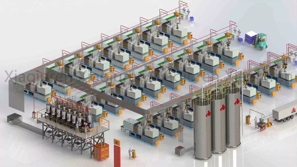
Start by assessing the basics:
- How many injection molding machines do you have?
- What is the layout pattern — single row, double row, U-shape?
- Is there available space for centralized storage and material control?
✅ Pro Tip: Arranging machines in groups or rows helps reduce pipeline length and simplifies distribution planning.
Step 2: Plan the Central Raw Material Area
This is where your material journey begins. It typically includes:
- Bulk bag unloading stations or manual bag dump stations
- Material silos or multi-bin hoppers
- Optional pre-mixing units for virgin/recycled material blending
Choose a location that offers:
- Easy forklift access
- Minimal interference with production flow
Step 3: Add Drying and Dehumidification (If Required)
If you are processing hygroscopic materials (like PET, PA, or PC), material drying is essential.
Dryers should be placed:
- Between the storage area and distribution network
- Close to machines if drying smaller batches
- Properly ventilated to release hot air
✅ Typical setup: One centralized dehumidifying dryer connected to multiple drying hoppers for different materials.
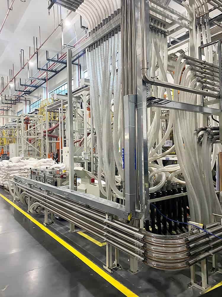
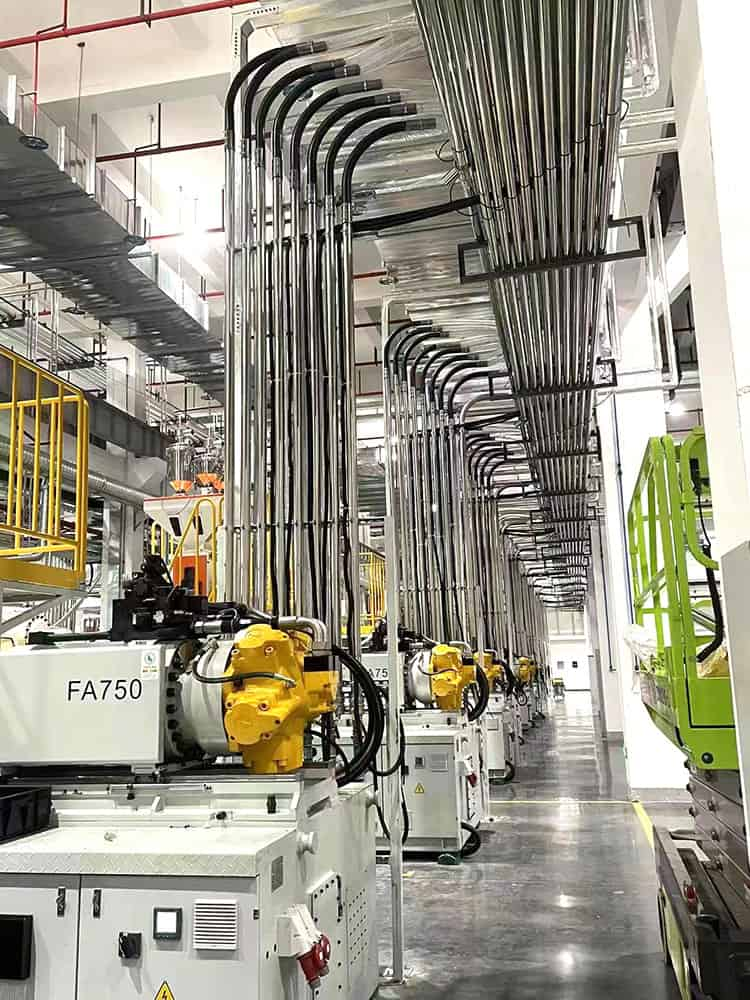
Step 4: Design the Vacuum Conveying Pipeline Network
This is the backbone of the central feeding system.
Key components include:
- Vacuum pump stations
- Stainless steel conveying pipes
- Material distribution valves
- Dust filters and pipe cleaning units
Layout guidelines:
- Keep pipe runs as short and straight as possible
- Avoid sharp bends and long horizontal runs
- Use color-coded or labeled pipes for easy identification
Step 5: Connect to Each Injection Molding Machine
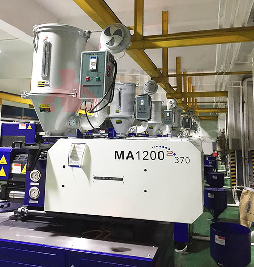
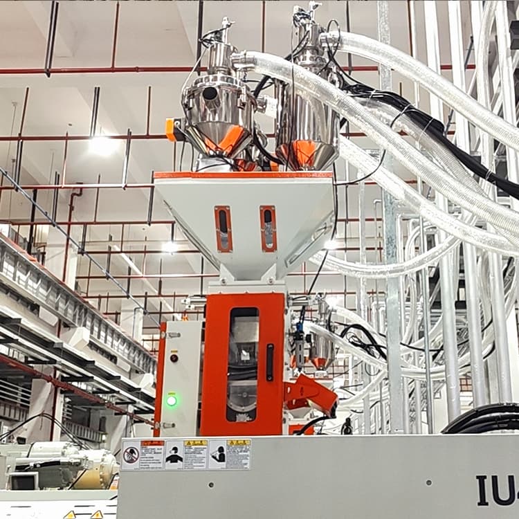
At each molding machine:
- Install a material receiver or hopper loader
- Add a mini dryer if local drying is needed
- Optional: install a low-level sensor to avoid material shortages
For applications requiring precise mixing, connect a gravimetric blender before feeding materials into the machine.
Step 6: Set Up Centralized Control and Monitoring
A control panel with PLC and touchscreen interface should allow:
- Real-time monitoring of material flow
- Automatic alerts for errors or pipe blockages
- Scheduling of feeding times and material types for each machine
✅ Advanced option: Add remote monitoring or data logging for smart factory integration.
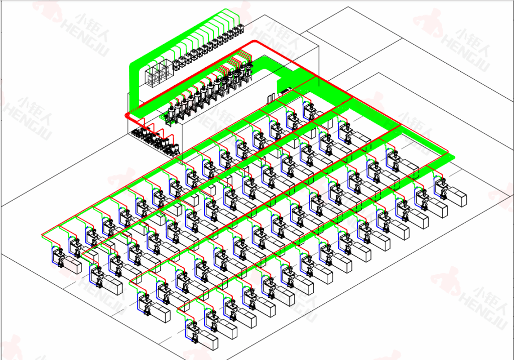
Suggested Layout Diagram (Optional Illustration)
- Left side: Raw material area (unloading, storage, drying)
- Center: Vacuum pump station and central control cabinet
- Right side: Injection molding machines with receiving hoppers
- Top view: Main pipelines with branches connecting each machine
Need a layout diagram customized to your factory? Let us know — we can help.
Conclusion
A successful central feeding system layout is more than just connecting pipes — it’s a strategic plan for clean, automated, and scalable production.
By following the steps above, you can:
- Avoid material delays
- Improve overall efficiency
- Create a system that grows with your factory
👉 Want a free custom layout for your plant?
Send us your machine layout and material info — we’ll provide a tailored design and quote.
“Want a full overview of how a central feeding system works? Check our complete guide here.”
Ready to upgrade your material feeding system?
✉Request a Free Layout Plan
📋 Download Technical Brochure
Contact now
Email: Jenny@gdhengju.com


